3D Modeling for Printing
A complete guide from choosing modeling software to exporting models optimized for FDM printing.
⏱ Estimated time: 13 min
Procedure
🖥️ Choosing Modeling Software
The right software depends on your experience and the type of models you create. There are three main categories: parametric, organic, and mesh modeling.
🎯 By Level and Focus
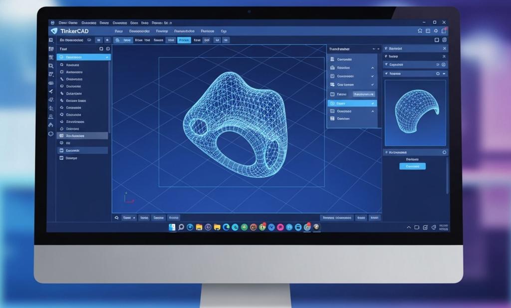
TinkerCAD — the perfect starting point for beginners
Free online · Czech · No installation
Drag-and-drop geometry right in your browser. You'll design your first part in 30 minutes.
- Type
- Parametric (CSG)
- Price
- Free (Autodesk account)
- Ideal for
- Boxes, holders, simple spare parts
- Platform
- Online (Chrome/Firefox)
Advantage: No installation, works on tablet and phone. The community shares ready-made templates.
Limitations: More complex organic shapes are impractical — go to Fusion 360.
Fusion 360 — the standard for hobbyists and professionals alike
Free for hobby use
Professional parametric CAD software with operation history, simulations, and CAM. It takes 2–4 weeks to learn.
- Type
- Parametric CAD/CAM
- Price
- Free (personal license) / $695/year
- Ideal for
- Functional parts, assemblies, mechanisms
- Platform
- Windows, macOS
Parametric History: Each operation can be modified retroactively — changing the dimension of the base automatically updates the entire model.
Assemblies Model multiple parts at once with constraints — ideal for joints, hinges, and moving mechanisms.
Blender — Organic Shapes and Figures
Free and open-source
Mesh modeling and sculpting for organic shapes, figurines, and miniatures. Steep learning curve.
- Type
- Mesh / Sculpt / Animation
- Price
- Free (GPL license)
- Ideal for
- Figurines, miniatures, decorative objects
- Platform
- Windows, macOS, Linux
Sculpt Mode: Model like clay — brushes to add, subtract, and smooth matter.
Print Toolbox addon: Built-in tool to check waterproofness and wall thickness before export.
📐 Basic Printing Rules
An FDM printer prints layer by layer. The model must take into account the physical limitations of the process—otherwise, the print will fail or require unnecessary support structures.
⚠️ The Most Common Mistakes Beginners Make
The Rules of Geometry — What FDM Can Do
Overhangs above 45° = necessary supports
An FDM printer cannot print into empty space. Each layer must be supported by the layer below it.
- Min. wall thickness
- 0.05 in (= 2 perimetry 0.02 in)
- Maximum safe overhang
- 45° without supports
- Min. hole diameter
- 0.08 in (smaller ones are covered with plastic)
- Minimum clearance for movement
- 0.01 in (joints, hinges)
❌ Error — thin pegs: A pin < 0.06 in is too thin — the nozzle "squeezes" it and does not fix it. Reinforce or add chamfer.
❌ Error — flat overhangs: Horizontal surface in the air with no support below it = 90° overhang. Reorient the model or add a chamfer.
✅ Tip — "Teardrop" otvory: For horizontal openings, use a teardrop shape instead of a circle — this eliminates the need for supports inside.
🏗️ Model orientation in the slicer
How to Properly Rotate a Model for Printing
💡 Orientation = the most important decision
The orientation determines the strength, the number of supports, the print time, and the surface quality all at once.
Layers ⊥ for load: Print the part stressed by bending with the layers perpendicular to the axis of the bend — otherwise it will crack between the layers.
The most critical area down: Place the most important (most visible) surface on the mat — without supporting scars.
Minimizing support structures Turn the model so that the overhangs are below 45° — you will save time and material.
🔩 Tolerances, Joints, and Assemblies
Parts that need to fit together require the correct tolerances. An FDM printer adds ~0–0.01 in of extra material—this must be compensated for.
📏 Recommended Tolerance Values
Tolerances for Different Types of Joints
Always print a test pin before making the final piece
These values are approximate—each printer and material behaves differently. Print some test cubes.
- Free movement
- 0.01–0.02 in per side
- Press-fit
- 0–0.01 in per side
- Screw threads (M3+)
- Heat-set insert > printed thread
- Snap-fit flexible part
- Thickness 0.06-0.08 in, length ≥ 0.31 in
Heat-set inserty: Use this recommendation while configuring your print.
Calibration pin: Print a 0.39 in diameter pin and measure with a caliper — deviation = your compensation offset.
🔗 Types of Print Connections
Overview of Installation Methods
Heat-set = most reliable for solid parts
Each type of joint has its own application—it depends on the force involved and how often it is disassembled.
Press-fit: We "press" the parts together without screws. Ideal for lids, covers and decorative parts.
Snap-fit: The flexible tab snaps into the cutout. Quick and repeated opening (boxes, cases).
Glue (CA/Epoxy) Second PLA glue. Epoxy on PETG and ABS. Sand the surface before gluing.
⚙️ Model Optimization for FDM
Small design adjustments can save hours of printing time, kilograms of material, and hundreds of crowns. Design with an understanding of how the slicer will "process" the model.
💡 Tips for Fewer Supports and Better Results
Design Tips for FDM
Chamfer instead of Fillet on bottom edge = zero support
Minor changes in CAD will dramatically reduce printing complications.
Chamfer instead of fillet (rounding): Use a 45° chamfer on the bottom edges instead of rounding — you eliminate the overhang without supports.
Mouse Ears: Add small circles (Ø 0.2-0.31 in, height 0.01 in) to the corners — prevents lifting and warping.
Division of large models: Divide the model larger than the pad into parts — exact surfaces at the cut point, pins for alignment.
Lightweighting: Internal pockets and cutouts save material and time without losing strength.
🧱 Slicer Settings for Functional Parts
Key Settings for Rigid Parts
Functional parts: Infill 40-60%, 4+ perimeters
The slicer translates the model into printer movements—the right settings are half the battle.
- Functional parts (infill)
- 40–60 % (Gyroid nebo Cubic)
- Perimeters
- 4–6 for mechanical parts
- Top/Bottom Layers
- 5–6 (prevents ceiling transparency)
- Layer Thickness
- 0.01-0.01in (Detail) / 0.01 in (Speed)
Gyroid infill: The most even distribution of force in all directions — ideal for parts stressed from multiple axes.
💾 Export and Pre-Print Check
Check your model before sending it to the slicer—geometry errors can cause hidden problems during printing.
📁 File Formats
STL vs. 3MF — Which One Should You Use?
3MF = modern standard, STL = old standard
If your slicer supports 3MF, always choose 3MF over STL.
- STL
- Only geometry, no colors or materials
- 3MF
- Colors, materials, slicer settings in one file
- OBJ
- Geometry + colors, without print settings
- STEP
- Parametric format for CAD-to-CAD exchange
3MF advantage: It preserves colors for multi-material printing and allows you to share the entire project with slicer settings.
🔍 Pre-print Checklist
What to Check in the Slicer
Red areas in the slicer = error in the model
Most slicers (PrusaSlicer, Bambu Studio, Cura) display errors using colors—orange/red = problem.
✅ Waterproof (manifold): The model must be closed without holes in the surface. In Blender: Print Toolbox → Check All.
✅ Correct size: Check the units! TinkerCAD exports in mm, Blender can export in cm.
✅ Normal out: All surfaces must point outside (outside normals). Inverted normal = slicer does not "see" the wall.
✅ No overlapping geometries: Two solids that overlap but are not merged (Boolean Union) = problems in the slicer.